Design Features
3U plug-in amplifiers
Dedicated control card for each amplifier
19 inch rack-mount design
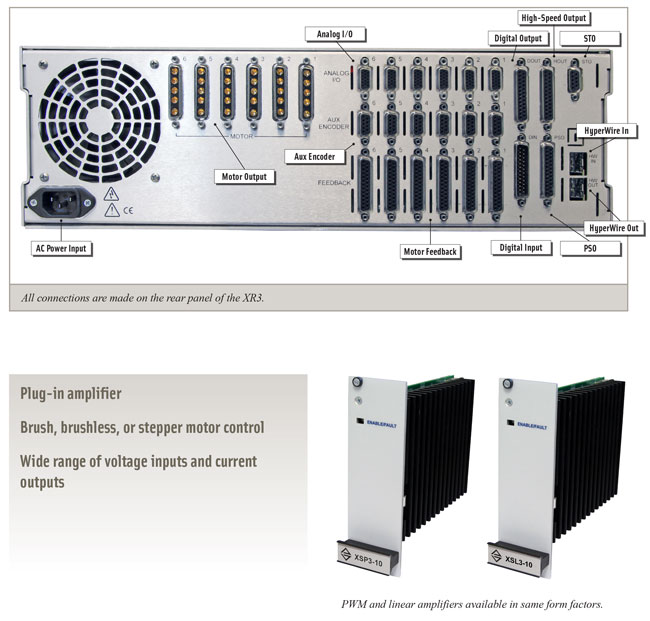
Flexible design provides the ability to drive brush, brushless, or stepper motors with the same amplifier
Up to 30 A peak output current
PWM or linear amplifier
Integral Safe Torque Off (STO)
Position Synchronized Output (PSO)
Integral power supplies
HyperWire® fiber-optic interface
Digital current, velocity, and position loops for improved motion stability
Integrated encoder multiplier for higher throughput and reduced wiring
NRTL safety certification and CE approval; follows the 2011/65/EU RoHS 2 Directive
The XR3 is a high-performance, six-axis drive rack with field replaceable front-mounted amplifiers. All versions are 3U in size, rack-mountable, and compatible with the Automation 3200 motion platform.
Featuring high-performance control electronics, the XR3 is Aerotech’s highest performing multi-axis controller. Both the current loop and servo-loop are closed digitally to assure the highest level of positioning accuracy and rate stability. This processing capability allows the XR3 to provide loop closure rates up to 20 kHz and to handle both digital and analog I/O processing, data collection, process control, and encoder multiplication tasks in real time.
Standard features for the XR3 include per axis brake control logic, auxiliary encoder feedback, and analog I/O expansion. Also standard are 16 opto-isolated inputs, 16 opto-isolated outputs, up to 12 high-speed differential outputs, 3 PSO external sync inputs, 3 TTL or isolated PSO outputs, 1 opto-isolated data-acquisition input, and 2 STO sense inputs.
The XR3 supports open-loop control, standard square-wave encoder feedback, analog input feedback control, and absolute encoder feedback.
Standard options for the XR3 include three different levels of integrated encoder multiplication including options that support dual-loop encoder feedback, drive-rack cooling options, rack or slide-type mounting options, and multi-axis Position Synchronized Output (PSO) I/O for low-latency, position-based process control.
Also available are a wide variety of extensions of the base PSO functionality. Track up to three encoders in real time with three-axis PSO or extend PSO's functionality to kinematic arrangements through the use of Aerotech's Part-Speed PSO feature.
The XR3 uses plug-in amplifiers supporting both linear and PWM topologies to control brushless, DC brush, or stepper motor types at up to 320 VDC operating voltage and 30 A peak current capability. The XR3 contains two configurable power supply sections to support a variety of motors with different operating voltages. When only one motor voltage is required, the power supply sections are joined together for even higher power capability. The XR3 supports up to three axes of Position Synchronized Output (PSO) for precise synchronization of external devices, over-voltage shunt controller, and external fans for high-power operation.
Specifications
XR3 Specifications
| Feature | Description |
|---|
| Number of Axes | 1 to 6 |
| Encoder Inputs | 2 through 12 depending on number of axes |
| Motor Style | Brush, Brushless, Stepper, Voice Coil |
| Dedicated Axis I/O on Feedback Connector | Three limit inputs (cw, ccw, home); three Hall effect inputs (a, b, c); three high-speed differential inputs (sin, cos, mkr for encoder); absolute encoder inputs; brake logic i/o; motor over-temperature input |
| Ability to Output Multiplied Encoder Signals | Yes, with the MX2 or MX4 option |
| Ability to Output Square Wave Encoder Signals | Yes |
| Primary Encoder and Auxiliary Encoder Input Frequency with Multiplication | Controller card option with:
MX1 option: 450 kHz primary encoder/square-wave only auxiliary encoder MX2 option: 2 MHz primary encoder/square-wave only auxiliary encoder MX4 option: 2 MHz primary encoder/2 MHz auxiliary encoder
|
| Primary Encoder Input Frequency – Square Wave | 10 MHz square wave frequency/40 MHz count rate |
| Secondary Encoder Input Frequency – Square Wave | 10 MHz square wave frequency/40 MHz count rate |
| Encoder Multiplication(3) | MX1 option: x16,384 primary encoder/square-wave only auxiliary encoder
MX2 option: x65,536 primary encoder/square-wave only auxiliary encoder
MX4 option: x65,536 primary encoder/x65,536 auxiliary encoder |
| Position Synchronized Output (PSO) | Standard:
Optional:
Two-axis PSO (includes two-axis Part-Speed PSO) Three-axis PSO (includes three-axis Part-Speed PSO) Two-axis Part-Speed PSO Three-axis Part-Speed PSO
|
| Internal Shunt Resistor | 40 W continuous; 400 W peak (5 seconds) |
| Communication Bus | HyperWire fiber-optic interface |
| Joystick Support | Yes |
| Current Loop Update Rate | 20 kHz |
| Servo Loop Update Rate | 8 kHz |
| Operating Temperature | 0 to 40°C |
| Storage Temperature | -30 to 85°C |
| Weight | 25 kg |
| Package | 3U rack mount with slice amps installed from front |
| Feature | XSL3-10-40 | XSP3-10 | XSP3-20 | XSP3-30 |
|---|
| Amplifier Type | Linear | PWM |
| Peak Motor Output Current (2 sec)(1) | 10 Apk | 10 Apk | 20 Apk | 30 Apk |
| Continuous Current | Load Dependent(2) | 5 A | 10 A | 10 A |
| Maximum Bus Voltage | 40 VDC (Bipolar) | 320 VDC |
| Maximum Power Amplifier Bandwidth(3) | 2 kHz
|
| PWM Switching Frequency | NA | 20 kHz |
| Minimum Load Inductance | 0 mH | 0.1 mH @ 160 VDC (1.0 mH @ 320 VDC) |
| Heat Sink Temperature (maximum allowable) | 75°C (All Amplifiers)
|

Dimensions
Ordering Information
XR3
| Option | Description |
|---|
| XR3 | Rack-mount digital amplifier chassis with integral DC power supply and HyperWire interface. Supports up to 6 axes of brush, brushless, or stepper motor amplifiers. |
Line Voltage
| Option | Description |
|---|
| -VL1 | 115 VAC input |
| -VL2 | 230 VAC input |
| -VL3 | 100 VAC input |
| -VL4 | 200/208 VAC input |
Bus Voltage 1
| Option | Description |
|---|
| -VB1 | ±10 VDC (200 W power supply), bipolar |
| -VB2 | ±20 VDC (200 W power supply), bipolar |
| -VB3 | ±30 VDC (200 W power supply), bipolar |
| -VB4 | ±40 VDC (300 W power supply), bipolar |
| -VB5 | ±80 VDC (300 W power supply), bipolar |
| -VB7 | 160 VDC unipolar |
| -VB8 | 320 VDC unipolar |
Bus Voltage 2
| Option | Description |
|---|
| -VB0 | Not wired |
| -VB1 | ±10 VDC (200 W power supply), bipolar |
| -VB2 | ±20 VDC (200 W power supply), bipolar |
| -VB3 | ±30 VDC (200 W power supply), bipolar |
| -VB4 | ±40 VDC (300 W power supply), bipolar |
| -VB5 | ±80 VDC (300 W power supply), bipolar |
| -VB7 | 160 VDC unipolar |
| -VB8 | 320 VDC unipolar |
Split Bus
| Option | Description |
|---|
| -SB0 | Axis 1-6 bus voltage 1 (no split) |
| -SB1 | Axis 1 bus voltage 1, axis 2-6 bus voltage 2 |
| -SB2 | Axis 1-2 bus voltage 1, axis 3-6 bus voltage 2 |
| -SB3 | Axis 1-3 bus voltage 1, axis 4-6 bus voltage 2 |
| -SB4 | Axis 1-4 bus voltage 1, axis 5-6 bus voltage 2 |
| -SB5 | Axis 1-5 bus voltage 1, axis 6 bus voltage 2 |
Controller Cards
| Option | Description |
|---|
| -CT0 | No controller card |
| -CTN | Controller card without multiplier |
| -CT1 | Controller card - 450 kHz x16384 multiplier (primary), no multiplier (auxiliary) |
| -CT2 | Controller card - 2 MHz x65536 multiplier (primary), no multiplier (auxiliary) |
| -CT4 | Controller card - 2 MHz x65536 multiplier on primary and auxiliary |
Amplifier Cards
| Option | Description |
|---|
| -P0 | No amplifier |
| -P1 | XSP3-10 amplifier |
| -P2 | XSP3-20 amplifier |
| -P3 | XSP3-30 amplifier |
| -L1 | XSL3-10-40 amplifier |
Cooling
| Option | Description |
|---|
| -C0 | Built-in fan pulls cooling air from left side |
| -C1 | No cooling fan, exterior cooling required through vented covers |
| -C2 | 1U-high fan tray for cooling |
Line Cord
| Option | Description |
|---|
| -LC0 | No line cord |
| -LC1 | USA 115 VAC compatible line cord |
| -LC2 | USA 230 VAC compatible line cord |
| -LC3 | German compatible line cord |
| -LC4 | U.K. compatible line cord |
| -LC5 | Israel compatible line cord |
| -LC6 | India compatible line cord |
| -LC7 | Australia compatible line cord |
Mounting Options
| Option | Description |
|---|
| -MT0 | Rack-mounted configuration |
| -MT1 | Rack-mounted configuration with drawer slides |
PSO
| Option | Description |
|---|
| -PSO1 | One-axis PSO (default) |
| -PSO2 | Two-axis PSO |
| -PSO3 | Three-axis PSO |
| -PSO5 | Two-axis Part-Speed PSO |
| -PSO6 | Three-axis Part-Speed PSO |
Internal Shunt (Optional)
| Option | Description |
|---|
| -SI0 | No internal shunt |
| -SI1 | Internal shunt, first bus |
| -SI2 | Internal shunt, second bus |
| -SI3 | Internal shunt, first and second bus |
Integration (Required)
Aerotech offers both standard and custom integration services to help you get your system fully operational as quickly as possible. The following standard integration options are available for this system. Please consult Aerotech if you are unsure what level of integration is required, or if you desire custom integration support with your system.
| Option | Description |
|---|
| -TAS | Integration - Test as system
Testing, integration, and documentation of a group of components as a complete system that will be used together (ex: drive, controller, and stage). This includes parameter file generation, system tuning, and documentation of the system configuration. |
| -TAC | Integration - Test as components
Testing and integration of individual items as discrete components that ship together. This is typically used for spare parts, replacement parts, or items that will not be used together. These components may or may not be part of a larger system. |